Overview
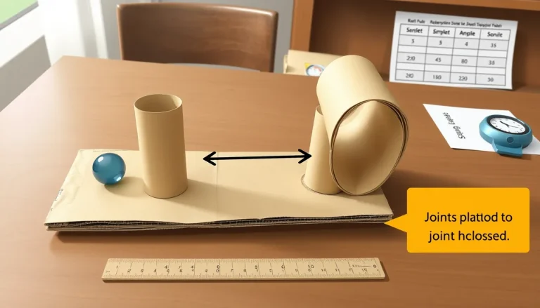
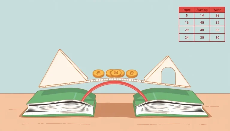
This project invites children to act like structural engineers. Using only cardboard tubes, flat cardboard, and paper, they will design a bridge, construct it, and then test how much weight it can hold before breaking. The activity highlights concepts such as forces, load distribution, and material strength while encouraging iterative design.
Before you begin
- Choose a work surface that can safely support the bridge and the test weights (a sturdy table or a cleared floor area).
- Gather all materials and tools before starting. A few minutes of preparation prevents interruptions during the build.
- Adult supervision is recommended for cutting cardboard and handling any heavy test weights.
Materials
- Empty toilet‑paper or paper‑towel tubes (at least 10, length ~15 cm each).
- Flat cardboard sheets (e.g., from a cereal box or shipping box).
- Plain printer paper (for reinforcement and decorative elements).
- Masking tape or painter’s tape (paper‑friendly, easy to remove).
- Scissors or a craft knife (adult‑only).
- Ruler or measuring tape.
- Weights for testing – small sandbags, a bag of rice, or a stack of coins (each weight should be known in grams).
- Pen or pencil for marking measurements.
Design constraints and success criteria
- Span: The bridge must cross a gap of 30 cm (measured from support to support).
- Materials: Only the items listed above may be used. No additional wood, plastic, or metal is allowed.
- Dimensions: The bridge deck (the part that carries the weight) may be no wider than 10 cm.
- Success criteria: Record the maximum weight the bridge supports before any part collapses or the deck sags more than 2 cm.
- Iterative improvement: After the first test, you may rebuild or reinforce the bridge and retest to see if the load capacity increases.
Steps
- Plan the design. Sketch a simple bridge on paper. Common shapes for cardboard include a truss (a series of triangles) or a beam with side “walls.” Identify where each tube will serve as a vertical support, diagonal brace, or top/bottom chord.
- Prepare the components. Cut tubes to the desired lengths using scissors. Typical lengths: 15 cm for vertical supports, 20 cm for diagonal braces, and 30 cm for the top and bottom chords that span the gap.
- Build the frame. Lay out the bottom chord (the base) on the table, then attach vertical tubes at 5 cm intervals using tape. Connect the top chord to the tops of the verticals, forming a rectangular frame.
- Add diagonal bracing. Tape diagonal tubes between the top of one vertical and the bottom of the adjacent vertical to create triangles. Triangles give the structure rigidity because forces are spread along multiple members.
- Create the deck. Cut a piece of flat cardboard to 30 cm × 10 cm. Tape it securely on top of the frame. For extra strength, fold a sheet of paper lengthwise and tape it beneath the deck as a sandwich layer.
- Place the bridge on supports. Position the bridge so that each end rests on a sturdy block or the edge of the table, creating the 30 cm span.
- Test the bridge. Gradually add weight to the middle of the deck. Use a small container so you can add weight in measured increments (e.g., 50 g at a time). Observe when the bridge first shows a noticeable sag (>2 cm) or when a tube breaks.
- Record the results. Note the total weight at the point of failure in the data table below.
- Iterate. If time allows, redesign a weak area (for example, add more diagonal braces or use extra paper layers) and repeat the test. Compare the new maximum weight to the original.
What to observe or measure
During testing, record the following for each trial:
| Trial | Design notes (e.g., added brace) | Weight supported before failure (g) |
|---|---|---|
| 1 | ||
| 2 | ||
| 3 |
The science explained
When a weight is placed on the bridge, gravity pulls the weight straight down. The bridge must convert this downward force into internal stresses that travel through its members. Triangular trusses are especially effective because each side of a triangle experiences either tension (being pulled) or compression (being squeezed), and the shape prevents the structure from changing shape.
Cardboard is a lightweight, layered material. Its strength comes from the corrugated flutes inside the sheet and the rigidity of the tube walls. However, cardboard can buckle when compressed, especially if the load is concentrated on a small area. Adding paper layers or using multiple tubes in parallel spreads the load, reducing stress on any single piece.
Measuring the maximum weight before failure gives a practical sense of how much stress the cardboard can tolerate. Re‑designing and retesting demonstrates the engineering process: hypothesize a change, build, test, and evaluate the outcome.
Troubleshooting
- Bridge collapses instantly. Check that all joints are firmly taped. Loose joints act like hinges and cannot transfer load.
- Deck sags but does not break. Add a second layer of cardboard or a strip of paper under the deck to increase stiffness.
- Tube walls split at the ends. Reinforce the ends with a small piece of flat cardboard wrapped around and taped.
- Weight distribution is uneven. Place the test weight in the center of the deck. If using a container, ensure the load sits symmetrically.
Try another version
After mastering the basic bridge, experiment with one of these variations:
- Longer span: Increase the gap to 45 cm and observe how the design must change to stay strong.
- Different shape: Build an arch bridge using curved cardboard strips; compare its load capacity to the truss design.
- Material substitution: Replace some cardboard tubes with rolled paper (tight paper rolls) to see how material stiffness affects performance.
Cleanup and disposal
Collect all cardboard pieces and recycle them according to your local guidelines. Tape residues can be peeled off and discarded with regular waste. Store any reusable tubes in a zip‑lock bag for future projects.
Related terms
- Load
- The force exerted on a structure, usually measured in newtons or grams.
- Stress
- Internal resistance of a material when a load is applied.
- Bridge
- A structure built to span a gap and support loads.
- Beam
- A horizontal structural element that carries load.