Orientation
This activity is an engineering challenge where students act as bridge engineers. They must design a bridge that spans a gap, construct it from everyday popsicle sticks, and then determine how much weight it can support before breaking. The project integrates hands‑on building, measurement, and basic physics concepts such as tension, compression, and the role of triangles in trusses.
Before You Begin
- Workspace: Use a sturdy table with a clear 35‑cm gap (about 14 inches) between two supports. Protect the surface with newspaper or a disposable tablecloth.
- Adult supervision: Required for cutting sticks, handling glue, and setting up the load‑test apparatus.
- Safety: Ensure children do not stand directly under the bridge while weights are added. Keep small parts away from younger siblings who might ingest them.
Materials
- Standard wooden popsicle sticks (11.3 cm × 1.0 cm) – up to 50 sticks per bridge.4
- White school‑glue or white wood‑glue (no other adhesives).4
- Cutting tool (scissors or hobby knife) – used only by an adult.
- Ruler or measuring tape.
- Construction paper for the deck (large enough for a match‑box car to roll).
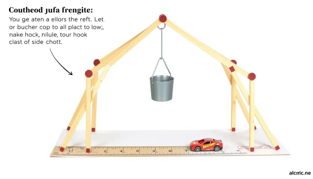
- Bucket (≈12 inches tall) and a sturdy hook or “B‑line S‑hook” for the load test.1
- Weight material – sand, water in a sealed container, or a set of small kitchen scales and metal washers.
- Scale for measuring the bucket’s total weight.
Design Constraints and Success Criteria
These rules keep the challenge fair and focus attention on engineering principles:
- Stick limit: No more than 50 sticks may be used. Sticks can be trimmed or cut, but cannot be shredded or laminated.4
- Span: The bridge must clear a 35 cm gap without touching the supports in the middle. A recommended overall length of at least 40 cm helps avoid the bridge slipping through the gap.4
- Deck width: A paper deck must be wide enough for a match‑box car (≈2 cm) to travel across.
- Load plate: The top of the bridge must support a 5 cm × 5 cm square plate that the bucket hangs from.4
- Success criteria: Record the maximum weight the bridge holds before failure. Aim for a weight that exceeds the average of the class (e.g., >5 kg) or simply note the highest value achieved.
Step‑by‑Step Procedure
1. Plan Your Truss
- Choose a truss style. The Warren truss, which uses alternating diagonal triangles, is beginner‑friendly and distributes load evenly.2
- Sketch a side view showing top chord, bottom chord, and diagonal web members. Mark where the load plate will attach (center of the top chord).
- Estimate the number of sticks needed for each part. Keep a tally to stay under the 50‑stick limit.
2. Build the Bridge
- Lay out sticks for the bottom chord (the “floor”). Glue sticks side‑by‑side to reach at least 40 cm.
- Construct the top chord in the same way, parallel to the bottom chord, leaving space for the web triangles.
- Assemble the diagonal web members: glue each stick between the top and bottom chords to form a series of equilateral triangles (≈2.5 cm sides). Alternate the direction of each diagonal as in a Warren truss.
- Reinforce joints by adding a second stick at right angles (a gusset) where two members meet. This adds strength without using many extra sticks.
- Attach the construction‑paper deck to the bottom chord with a thin line of glue. Ensure the deck is flat and centered.
- Allow the glue to dry completely (minimum 30 minutes, longer if possible).
3. Set Up the Load Test
- Secure the bridge on the two supports so that the gap underneath the middle is clear.
- Clip the B‑line S‑hook to the center of the top chord, directly under where the 5 cm loading plate will sit.
- Hang the empty bucket from the hook. The bucket should be about 12 inches (30 cm) below the bridge to avoid interference.
4. Conduct the Strength Test
- Gradually add weight to the bucket. Add small increments (e.g., 0.5 kg or a few sand packets) and pause after each addition.
- Observe the bridge for any signs of strain: bending, cracking of glue joints, or audible creaks.
- When the bridge finally collapses or the hook pulls free, stop adding weight.
- Carefully remove the bucket and weigh it on the scale to record the total load the bridge sustained.
- Document the result in the data table (see below).
What to Observe and Measure
During the test, record both qualitative and quantitative data:
- Maximum load (kg or lb): The total weight the bucket held at failure.
- Failure mode: Did the bridge snap at a joint, did a diagonal break, or did the top chord bend?
- Deformation: Approximate how far the bridge sagged before breaking (measure with a ruler if visible).
- Time to failure: Not essential, but noting how many minutes the loading took can help compare strategies.
Use the blank data table provided to keep results tidy for each trial.
Data Table
| Trial # | Bridge Design (e.g., Warren) | # Sticks Used | Maximum Load (kg) | Failure Mode |
|---|---|---|---|---|
| 1 | ||||
| 2 | ||||
| 3 |
Variables, Controls, and Repeated Trials
This is an engineering challenge rather than a hypothesis‑driven experiment, but you can still practice scientific rigor:
- Independent variable: The bridge design (e.g., number of diagonal members, stick layout).
- Dependent variable: Maximum load the bridge supports.
- Controlled variables: Stick type, glue type, span distance, loading method, and weight increments.
- Repeated trials: Build at least three bridges with the same design to see natural variation. Record each trial in the table.
Troubleshooting
- Bridge collapses immediately with a tiny load: Check that joints are fully dry and that each diagonal is glued on both sides. Reinforce weak points with extra gusset sticks.
- Bridge slides off the supports: Ensure the bottom chord rests flat on the supports and that the ends extend past the gap by at least 2 cm.
- Glue oozes out and weakens joints: Apply a thin, even layer of glue; excess glue can act as a hinge rather than a solid bond.
- Weight addition is uneven: Use a container that can be filled gradually (sand or water) and level the bucket before each addition.
The Science Explained
Bridges work because they turn a vertical load (the weight of a vehicle or, in this case, a bucket) into internal forces that the materials can handle. In a truss bridge, the triangular geometry forces most members into either tension (being pulled) or compression (being squeezed). Sticks are much stronger in compression than in tension, so engineers place the top chord under compression and the bottom chord under tension. The diagonal web members transfer load between the two chords, preventing any single stick from carrying too much force.
The Warren truss uses alternating diagonals, which spreads the load evenly and reduces the number of different member lengths needed—ideal for a limited supply of sticks. When you add weight, the forces increase until a joint or stick can no longer resist the stress, and the bridge fails. Observing where the failure occurs tells you whether the design provided enough tension or compression support.
Next Steps
After the first round of testing, encourage students to redesign based on their observations. Possible modifications include adding more diagonal members, using longer sticks for the top chord, or creating a laminated beam by gluing two sticks together (if allowed by your rules). Re‑test the new design and compare results in the same data table to see how engineering decisions affect strength.
For a classroom extension, groups can each adopt a different truss style (Warren, Pratt, or Howe) and present a short report on which carried the most load and why.
Related terms
- Compression
- A force that pushes or squeezes a material, trying to shorten it.
- Tension
- A force that pulls or stretches a material, trying to lengthen it.
- Truss
- A framework of triangles used in bridges and roofs to distribute loads efficiently.
- Load plate
- A small, flat surface attached to the bridge where weight is applied during testing.
Sources & references
- Popsicle Bridge Instructions, Tiger Science Challenge. https://www.rit.edu/ntid/sites/rit.edu.ntid/files/outreach/tsc/PopsicleBridgeInstructions20.pdf
- How to Build a Warren Truss Popsicle Stick Bridge, Avanza STEM. https://www.avanzastem.org/projects/popsicle-stick-bridge
- Junior Design – Popsicle Bridge, Kwantlen University. https://www.kpu.ca/sites/default/files/FacultyofScienceHorticulture/juniordesign-popsiclebridge.pdf